
Most dry bulk (powder, pellet, flake, granule, chip) handling plants are built by assembling together and interfacing a series of equipments that perform specific tasks like storing, de-bagging, conveying, feeding, mixing, blending and weighing these powders to required final process specifications.
Because each operation requires equipments specifically designed for each function, matching the equipment and process inputs to outputs becomes the key issue in system design.
If the answer to any of these questions below is yes, chances are you will need to troubleshoot each component to ensure the longevity and performance of your system:
Do you encounter performance problems with engineered systems due to the undefined and unpredictable behavior of bulk powders?
Have you experienced reduced or increased throughputs? Are you familiar with inconsistent flow patterns and line blockage, flow difficulties?
Have you dealt with wear and abrasion problems?
Are you concerned about dust emission beyond specified limits?
Do you worry about mechanical stress on equipment?
Have you ever faced high power requirements or motor failures?
All these problems lead to downtimes which finally affect plant productivity.
As a plant engineer responsible for smooth running of the plant, learn how to troubleshoot each component to optimize the efficiency of your entire system. While major problems may require vendor assistance, most issues in a poorly performing plant can typically be traced back to the performance of individual units in the system.
You must first make sure you thoroughly understand the principles of operation for each unit equipment. Review operating principles and features to effectively troubleshoot and avoid production delays and downtime.
Part I of this article will troubleshoot 5 common components that are part of a typical bulk handling system: (Watch this space for Part II )
Rotary valves
Filters
Instrumentation
Bends
Chutes
ROTARY VALVES:
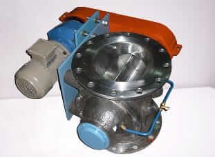
These units are used to provide metered feeding generally into a pressurized pneumatic conveying line and occasionally into a gravity receptacle.
Check your Rotary Airlock regularly for the following:
a. Is there blowback?
All rotary valves will leak the air or conveying gas that is used in the downstream pneumatic conveying system. This is because there is a gap between the stator and the rotor and the higher the gap, the greater the leak. Manufacturers have to compromise between having a large number of rotor vanes to minimize leakage (this simulates the labyrinth seal principle) and ensuring that material does not “wedge” into the vane pockets. The best compromise normally gives a 6 or 8 vaned rotor. If the pressure drop is high in the pneumatic conveying line, it may be worthwhile to consider a suction system instead of a pressure system as this will ensure that there is no blowback
b. Check if you are getting rated capacity
Rotor speed is an important consideration since peak performance is obtained only in a particular narrow speed band. High speeds do not necessarily mean high throughputs since at higher speeds the rotor pockets will not have sufficient time to collect material fully as they move across the inlet opening. Filling efficiency is a critical factor and is best practically measured prior to placing order by sending some material to the supplier works for testing.
c. Check for Excessive noise and vibration
d. Check for Wear
FILTERS:
are used for separating air and the material. The unit is designed to comply with stringent Environmental Pollution norms and has built-in heavy duty filters that discharge clean air at less than 50 mg/Cum. emission to the atmosphere.
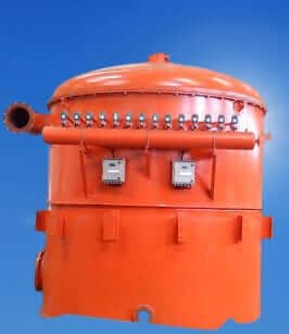
Check your filters for
a. High pressure drops across filters: Optimum timings conserve compressed air which is not often noticed and considered. Inlet designs should ensure that as much of the product is separated prior to the air mass passing through the filter bunk. This is done by having tangential entries / baffles etc. within the entrance section of the filter unit. Initial daily checks of the pressure drop across the filter body and the top plenum chamber are essential to confirm that filtration is taking place optimally. Once the primary filter coat is formed and the cleaning cycles are optimized, the pressure drop differential between these two areas will generally remain constant over a long period of time.
b. “Puffing” of filter bags: The selection of the filter cloth and the air to cloth ratio is different for different applications and different materials. Many companies make the mistake of conveying different materials of similar bulk densities in the same pipelines using the same filter. If this is not planned beforehand with the system components selected accordingly, major problems will result due to incompatibility between the material being handled, the filter cloth and the cloth area available. The filter must be sized for proper can velocities, filtration velocities and cloth area. Compromises in these areas may not result in any problems initially but difficulties will surface as the plant grows older.
c. Poor discharge from filters: Cleaning cycles in reverse pulse jet filters have to be optionally set and this can be done only after a period of daily operation once the plant is up and running. It is tempting to have small intervals between cleaning pulses and large pulse timings on the assumption that the filter gets cleaned better. What would really happen with such ambition is that the cloth tends to give up its primary filter coat quickly leading to filtration problems. Pulse duration and frequency should ensure that the primary filter coat is retained while the secondary layer falls off.
d. Uncleaned filters: It is prudent to have a transparent section on the filter casing to observe conditions of filter bags during cleaning and non-cleaning periods. Such viewing windows should have manual wipers since fine powders can coat the inside of the transparent element and impede visibility
e. Broken bags: they will leave telltale deposits of powders on the plenum chamber where the filter element is fitted in. Removing the cover will show these areas. More expensive methods and instrumentation are available for online detection of broken bags but these should be installed only for very special and critical applications.
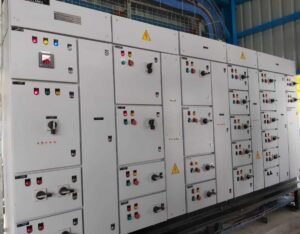
INSTRUMENTATION :
By far the most problems in bulk handling plants relate to instrumentation and control of the system operations.
a. Level Sensors: These tiny instruments can cause malfunction of the entire system! So tread carefully while choosing the type of level sensor for your material. For critical applications it would be better to have back-up sensing either with a second level sensor or with a load cell system.
– Vibrating fork: The vibrating fork units perform well where the vibration amplitudes get effectively dampened by the bulk material in contact with the forks. If your material is light and fluffy, chances are, the vibrations do not get dampened enough for a signal to be generated and sensing fails. Remove the instrument and check it separately by energising and dipping the instrument in the material to see behaviour. Some units have provision to alter the vibration characteristics and this could be tried out.
– Capacitance: The material characteristics influence performance to a great extent and no property of the material is too insignificant to ignore. Typical problems relate to the inability of the unit to sense capacitance change due to moisture, probe insensitivity due to coated powder deposits and inadequate probe surface. The plant engineer can try and adjust set points after trial and error but this procedure must be understood and applied
-Electromechanical (yo-yo) Type:: The mechanical “yo-yo” unit is simple and easy to install and use and its most vulnerable feature is the tendency to get embedded in the powder mass. You can easily rectify this by adjusting belt length.
b. Load Cells:
As an engineer working with bulk handling plants, it’s important to select the proper load cell for your application. Avoid over specifying accuracy requirements and consider production and marketing needs. Pre-select the type and number of load cells for the given application to ensure proper performance. Troubleshooting may require a qualified electronic engineer, but problems are generally easily resolved by tinkering with the electronics.
c. Enclosures: Dust is all pervasive and omnipotent. Check to see that there is no way dust can enter instrumentation or panel box internals.
Bends:
Are you choking your lines?
When it comes to vertical bends, make sure you’ve got a drop leg on the riser for easy cleaning. And for those long horizontal pneumatic conveying lines, add internally threaded sockets welded at an angle every 2 to 3 meters. They’ll be capped most of the time, but in case of a choke-up, you can blast some compressed air through those babies and get things moving again. Don’t let a little choke-up ruin your day – get your system flowing smoothly!
Chutes:
Is your material stuck?
The connection between unit equipment is crucial for smooth product flow, and chutes or pipe ducts are the go-to options. However, when the layout doesn’t permit vertical gravity feed, you’ll need to incline your chutes for seamless material movement. The choice here is between gravity chutes and chutes with flow aid devices such as electric vibrations or fluidized porous media. Your product characteristics should be the primary consideration when selecting chute type, and it’s important to finalize chute designs before ordering equipment.
Matching dimensional openings and interconnecting different suppliers’ equipment can be a real headache, but equipment suppliers may be willing to make minor changes to suit downstream units. To avoid costly changes during installation, it’s best to finalize the layout and matching interfaces during the ordering stage. This will ensure your materials flow with ease, and you avoid getting stuck in a costly situation!
For a checklist and manual, contact marketing@scorpiobmh.com
I look forward to engaging with my readers!
FAQs: Bulk Material Handling Component Performance (Part 1 of 2)
1. Why is monitoring bulk handling component performance critical?
Regular checks prevent unplanned downtime, material spillage, excessive wear, and energy waste, ensuring smooth operations and cost efficiency.
2. What are the 9 key checkpoints for bulk handling components?
(Part I covers the first 5):
Conveyor Belt Tracking
Pulley Lagging Condition
Idler Roller Functionality
Skirting & Belt Seal Integrity
Transfer Chute Wear Patterns
(Part II covers the remaining 4.)
3. How does improper conveyor belt tracking affect operations?
Misaligned belts cause:
Material spillage
Edge damage to belts
Increased energy consumption
Premature pulley/idler wear
4. Why is pulley lagging important?
Pulley lagging:
Improves traction between belt and pulley.
Reduces slippage and belt wear.
Extends component lifespan.
5. What are signs of failing idler rollers?
Look for:
Unusual noise (grinding/squeaking)
Seized or wobbly rollers
Material buildup around rollers
6. How does skirting impact bulk handling efficiency?
Worn or misaligned skirting leads to:
Dust leaks & spillage
Belt damage
Safety hazards
7. What causes excessive transfer chute wear?
Abrasive materials
High-impact loading
Poor chute design/material selection
8. How often should these components be inspected?
Daily/Weekly: Visual checks (spillage, noise, misalignment).
Monthly: Detailed inspections (lagging, idlers, skirting).
Annually: Comprehensive audits.
9. Can component wear increase energy costs?
Yes! Faulty components (e.g., misaligned belts, seized rollers) force motors to work harder, raising power consumption by up to 20%.
10. Where can I learn about the remaining 4 checkpoints?
Read Part II of this series for checkpoints 6–9!
Key Takeaways for Readers
Proactive maintenance cuts costs and boosts productivity.
Partner with Scorpio BMH for performance audits and tailored solutions.