Bulkagram 19. April 24, 2023
In Part 1 of this paper, we covered 5 components that need to be troubleshooted for their effect on the bulk material handling system in use. You can access this article here:

Today we will troubleshoot the following components:
Flexible Spiral Conveyors: These units are generally applied to elevate powders over relatively short distances to feed reactors, vessels, hoppers etc from ground level. They consist of a centreless spiral auger driven at one end and encased in a polymer based tube. Feed of product is directly into the tube from a feed hopper. The spirals run at anywhere from 100 to 500 rpm. Typical problems include breakage or unravelling of the spiral, product compaction etc. It is advisable to purchase a small length of extra spiral when ordering the equipment to connect this on if the spiral breaks. Mechanical clamps can be made to add on one bit of spiral to the main spiral without any adverse effect on performance. Most breakage is at or near the drive end and results from high inertial torque during startup on load and due to hard lumps in the material. Unravelled bits of spiral can also be removed (cut) and a new piece added. In some cases, the unravelled bit can be cut off and the rest of the spiral streteched to regain the original length. It is preferable to discuss these issues with vendors prior to order.
Aeromechanical conveyors: Again a common element in most bulk handling plants, this equipment is used to elevate powders over relatively short vertical distances to feed reactors, vessels, mixers etc.
A series of plastic discs are fitted at regular intervals on a wire rope assembly and this endless rope-disc assembly runs inside a twin tube arrangement connected by sprockets at regular intervals. Feed is at the lower end through a feed hopper and discharge at the other end. Problems in operation will include rope breakage, inadequate throughput. Broken ropes can be mended by adding on a separate piece. Low throughput can be correct by speed changes and by redesigning hopper feed.
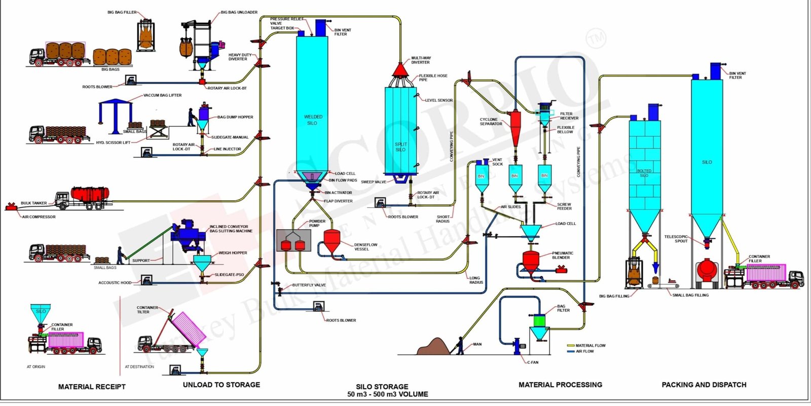
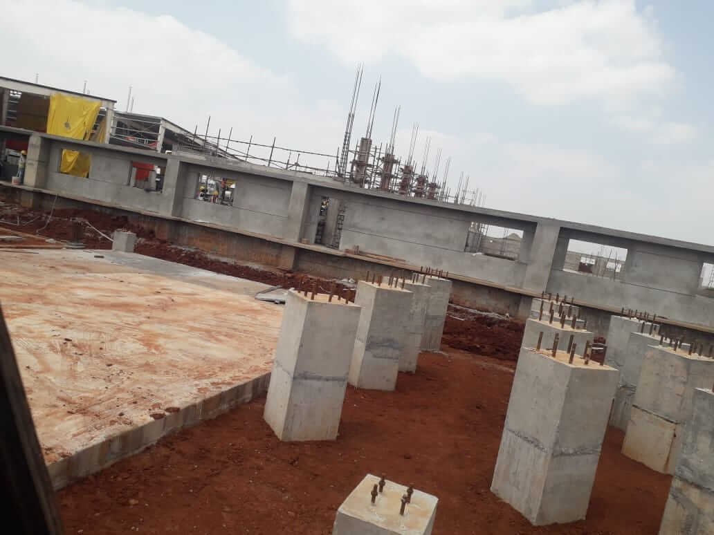
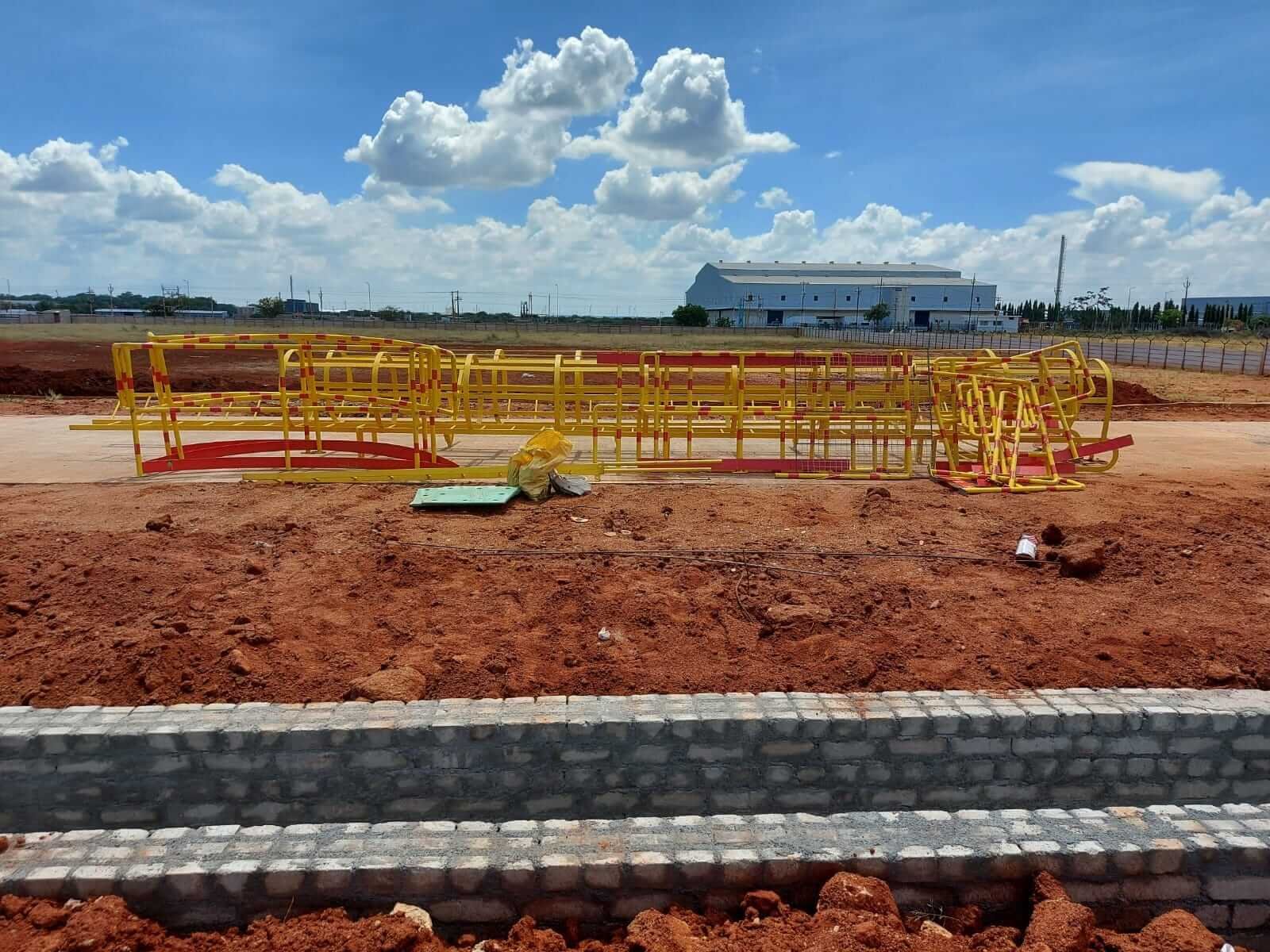
Plant Layout: Much heartbreak and headache can be avoided by simply walking around the bulk handling plant and making changes to the layout if you have already built a plant and by making changes on the drawing board if you are in the process of building one. By far the best layout would be one wherein the bulk material utilizes gravity to the maximum extent possible. This has to be considered based on the cost of a vertical layout against the cost of a horizontal layout. This would again depend on land cost in the area where the plant is situated.
Bulk solids are influenced greatly by their angle of repose and to maintain this critical angle, large diameter conical bottom hoppers or silos would require large heights. To save on heights, a single large vessel could be split to two smaller ones but at the cost of headroom. When filling silos or hoppers with bulk solids, it is advisable to fill in centre so that the product forms a uniform central cone within the hopper. For two hoppers side by side with a central fill point and being fed from a single vessel above, the height would be much higher than if one were feeding the two vessels at the periphery of the vessels. The choice is between height and vessel filling pattern. The latter may prove to be the undoing of plant performance because of flow problems due to non uniform vessel fill.
Enclosures: Typical bulk handling plants have a considerable amount of unseen ambient dust in practical conditions and instruments, enclosures should generally be to IP65 or higher. Here again, the decision should be carefully made between the environment and the cost. If the handling system generally deals with large pellets or granules with little dust entrainment, enclosure specifications can be normally to IP55. If the system is handling fine powder of say 50 microns and below, the enclosure specifications should be reviewed carefully. Dust is all pervasive and omnipotent. It is therefore desirable to see that there is no way dust can enter instrumentation or panel box internals.
Pits and Pitfalls : Pits are very well known and popular devices in the layout of bulk handling plants. Once it is known that there is no headroom available for the layout of the bulk handling plant after building it, the first thing is to put equipment in a pit. This will immediately increase cost because of the excavation, sealing, waterproofing and drainage requirement of the pits in addition to the need for having a suitable cleaning system to clean the pits of dust and spillage accumulation. If no pit is permissible, one has to elevate and lower product over and over again to feed to different processes. It is best to avoid pits and this can only be done if the layout is planned in advance of placing equipment purchase orders.
Conveying Lines: In pneumatic conveying systems the best system is the one that has no bends since bends contribute to a major portion of the energy consumption and are also the causes for most of the choking and pressure drop problems for such plants. Deciding and modifying plant layouts well in advance of equipment ordering would enable an elegantly routed pneumatic conveying system that does not have to veer around skirting already installed equipment, columns, pipe racks, cable trays, steam, oil and water lines and a host of other hardware typical of a production plant. If the material handling system layout is handled as part of the overall utility planning, most problems will sort themselves out on the drawing board or on the computer screen. The risk with arbitrary plant routing changes to pneumatic conveying lines for circumventing plant obstacles would finally lead to inadequate system performance since the conveying capacity, pressure drop etc. of pneumatic conveying systems is critically dependent on the conveying pipe routing and number of bends.
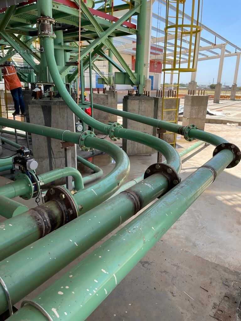
Running pneumatic conveying pipes next to hot lines like steam or hot oil lines are likely to lead to problems due to heating and cooling of the conveying air that can lead to product settlement or caking in the lines due to absorption of moisture condensate.
Maintenance Platforms and Support Structures: Because of the variety of equipment from different suppliers that make up a bulk handling plant, the maintenance areas and access to these areas for each equipment are fitted into the flow scheme. This would mean access platform and support structure that would need to be custom-built to allow maintenance personnel to approach the equipment for maintenance. This also needs to be part of the layout that has to be made prior to order placement. For equipments like filters having long filter elements the need to have almost 1½ times the height of the unit above the unit for filter removal may often pose problems due to headroom not being available. If this is communicated to the filter supplier, optional side removal units can be supplied often at considerable savings when compared to the need to increase headroom.
Wear and Abrasion: Bulk handling plants are extremely susceptible to performance problems due to the inherent nature of the product to the handled.Not only should the plants be designed to perform the task they are meant for but they should be built around the properties of the material that they will be handling. Materials like fly ash, silisca sand etc have excelled flow properties but their abrasive nature can create major wear problems. Even the specification of the bags which contain the bulk material will play a role in determining plant performance. When cutting paper abgs for example in a bag slitting machine, the abrasive nature of the paper would wear the knife hub down and lead to problems after a prolonged period of troublefree operation.
Bends in pneumatic conveying lines are the most likely candidates for rapid wear especially when the conveying is in dilute phase suspension flow mode. Various methods of preventing and minimizing bend erosion are available and needto be built in to the plant at the engineering stage. Vertical bends should also have a drop leg on the vertical riser to enable cleaning of choked lines.
Long Lengths of Pipe: For long horizontal pneumatic conveying lines, it is advisable to have small internally threaded sockets welded at an angle at 2 to 3m intervals. These will be capped under normal circumstances and can allow jetting of compressed air into the conveying line when the line has choked. This avoids the need to dismantle large sections of lines to clear chokes.
For a checklist and manual, contact marketing@scorpiobmh.com
I look forward to engaging with my readers!
Thankyou!